by Agnes Muszynska, Ph.D. Research Manager and Senior Research Scientist Bently Rotor Dynamics Research Corporation agnes@bently.com |
The following reply was sent by Agnes Muszynska to Dan Lubell, Sundstrand Power Systems, San Diego, CA, in response to an e-mail he sent after reading the March 1998 Orbit. He asks, "My question is in reference to the article on pump vibrations, 'ADRE® for Windows - instrumental in solving a complex vibration problem on a boiler feedwater pump.' There is mention of a 0.87X sub-sync due to 'pump whirl.' Pump whirl is a new term for me, and I was hoping I could be pointed in the direction of finding more about it. Is it an incompressible version of Alford's Force?" According to D. Childs (1993), H. Thomas suggested in 1958 that nonsymmetric clearances caused by eccentric operation of a steam turbine rotor can create destabilizing forces ("clearance excitation"). Most of Thomas' papers were written in German, and were not popular in the United States. Subsequently, J. Alford (1965) identified the same mechanism when analyzing stability problems of gas turbines. Since then, excitation forces due to clearance changes around the periphery of a turbine rotor were popularly called "Alford forces." H. Black (1974) suggested that pump impellers could also develop similar destabilizing forces. Since 1974, a large number of papers have been written based on theoretical analyses and various experimental tests conducted at many research centers. |
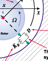
Figure 1 |
Bently Rotor Dynamic Research Corporation (BRDRC) followed Black's original research on pumps [3, 4], generally adopting the strategy that the rotating machine represents a system. The system must include solid elastic elements, as well as the fluid. BRDRC, through extensive modal perturbation testing in the laboratory, identified the fluid force model in radial clearances, such as in bearings, seals, or rotor-to-stator peripheries (including pump/compressor impeller/diffuser clearances) [7]. The fluid force model is based on the rotor-rotation-related, forward circumferential flow strength. If there are no special fluid preswirl, antiswirl, or other tangential injections, the average angular velocity of this flow is a fraction of the rotor rotative speed. This fraction is called the "fluid circumferential average velocity ratio," (lambda). It is a decreasing function of the rotor eccentricity (at an eccentricity ratio of "1," when the rotor touches the stationary part, lambda is equal to zero; the circumferential forward flow is replaced by other flow patterns; for example, axial and/or partially reverse circumferential). The average angular velocity has a physical meaning: it is the angular velocity at which the fluid damping force rotates [6,8]. Note, therefore, that the dashpot commonly used in the damping modeling is not stationary in the clearance, it rotates (Figure 1)! All flow-related "destabilizing forces" have the same characteristic (not only flow-related; for example, there exist similar "electromagnetic" destabilizing forces in electric machines). They are tangential forces (perpendicular to the rotor radial displacement), depending on the rotor lateral displacement. In linear rotordynamic modeling they are represented by coefficients of off-diagonal elements in the 2x2 "stiffness" matrix (the diagonal elements represent true stiffnesses). Usually these two off-diagonal elements have the same or nearly the same values and opposite signs. These signs indicate whether the forces are "forward" (same as the direction of rotation) or backward (against the direction of rotation, as in the case of a dry rub). While the Thomas and Alford definitions of the destabilizing tangential forces do not involve rotative speed, they do refer to "steam tangential efficiency" and torque. Both these parameters can be directly related to the resulting rotor rotative speed. A difference, however, exists in terms of the source of energy. In turbine peripheries, the energy is provided by the fluid itself (active system), while in bearings and seals of pumps and compressors, the energy comes from the rotor rotation driven by the external torque (passive systems). The average values of the circumferential flow are, therefore, different in all cases. Some people think that the frequency of whirl subsynchronous vibrations has to be 1/2 of the rotative speed. This is not so, even in any bearing. The truth is that they can be any frequency, if the circumferential flow is appropriately modified using an external energy source. |
Figure 2 |
The "destabilizing effect" observed in machinery in the form of rotor subsynchronous lateral vibrations with almost circular forward orbits (Figure 2) is the final result of the tangential force action exceeding the linear range. These subsynchronous vibrations are limit cycles of the self-excited vibrations, determined by the system nonlinearities and sustained by the rotating energy provided by the rotor. In "active" systems, the energy comes directly from the fluid. "Fluid whirl" and "fluid whip" are the best known of these vibrations (a special case is a "rotating stall"). Fluid whirl and whip are generic terms which include all previously used specific names, such as "oil whirl," "oil whip," "steam whip," "pumping whirl," "aerodynamic whip," etc. Fluid whirl is characterized by a frequency which is proportional to the rotor rotative speed and corresponds to one of the fluid-related natural frequencies of the system. The coefficient of this proportionality is slightly lower than the value of lambda. Note that the value [lambda times rotative speed] is close to one of the fluid-related natural frequencies of the system [6,8] Fluid whip is characterized by a constant, or nearly constant, frequency corresponding to one of the classical "mechanical" natural frequencies of the system, most often the one related to the lowest bending mode of the rotor. Note, however, that practically any mode of the system can get involved. |
Figure 3 |
In summary, the physical phenomena in rotor-to-stationary part radial, conical, or even axial clearances (balance piston!), filled with fluid (often, just air!) are very similar; the fluid gets involved in the circumferential motion. This motion creates tangential destabilizing forces. The final results of their action are measurable, unwelcome, mostly subsynchronous, vibrations of the rotor, either of the whirl or whip type (Figure 3). |
References |
1. Alford, J., Protecting Turbomachinery from Self-Excited Rotor Whirl, Journal of Engineering for Power, v.87, ser. A, No 4, Oct. 1965. 2. Black, H.F., Lateral Stability and Vibration of High Speed Centrifugal Pump Rotors, Dynamics of Rotors, 1974 IUTAM Symposium Proceedings, Springer Verlag, Berlin, Heidelberg, New York, 1975. 3. Black, H.F., Effects of Hydraulic Forces in Annular Pressure Seals on the Vibration of Centrifugal Pump Rotors, Journal of Mechanical Engineering Science, Vol. ll, No 2, 1969. 4. Black, H.F., Jensen, D.N., Dynamic Hybrid Bearing Characteristics of Annular Controlled Leakage Seals, Proceedings of Institution of Mechanical Engineers, Paper 9, vol. 184, 1970. 5. Childs, D.W., Turbomachinery Rotordynamics, John Wiley & Sons, Inc. New York, Chichester, Brisbane, Toronto, Singapore, 1993. 6. Muszynska, A., Whirl and Whip -- Rotor/Bearing Stability Problems, Journal of Sound and Vibration, Vol. 110, No 3, 1986. 7. Muszynska, A., Modal Testing of Rotors with Fluid Interaction, International Journal of Rotating Machinery, Vol. 1, No 2, 1995. 8. Muszynska, A., Bently, D.E., Fluid-Induced Instabilities of Rotors: Whirl and Whip -Summary of Results, Orbit, March 1996, 9. Thomas, H., Instabile Einenschwingungen von Turbinenläufern angefacht durch die Spaltströmungen Stopfbuschen und Beschauflungen, Bull. de l'Aim, 71, 1958. |